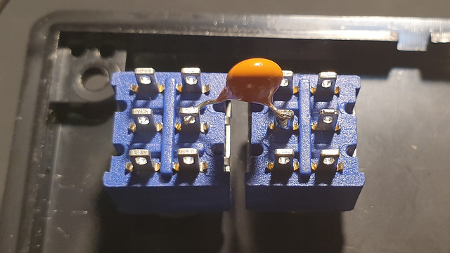
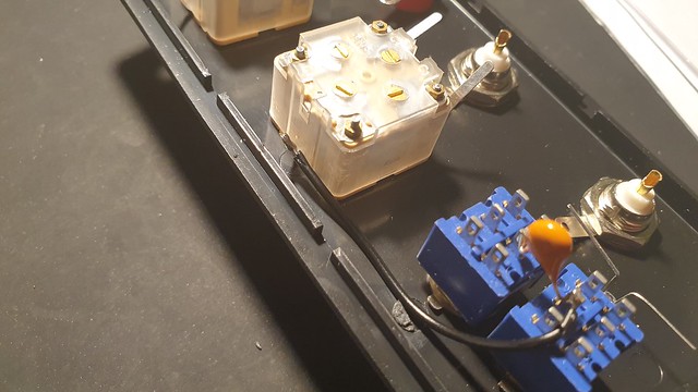
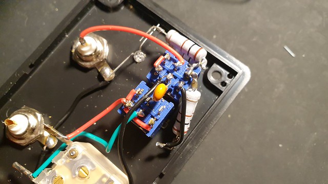
Now that the two toroids are prepared, and everything is already mounted into the enclosure lid, we can start soldering it all together.
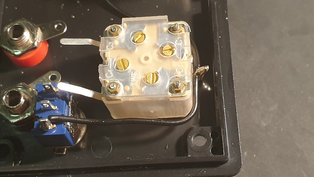
And here I can already tell you some things that I would have done differently if I knew upfront. The two switches are placed too close together. The T2 will not fit between the two switches, and the black wire will be in the way of the resistors. I can’t change the placing of the switches anymore, but you will notice in pictures to come, that I laid the black cable slightly differently.
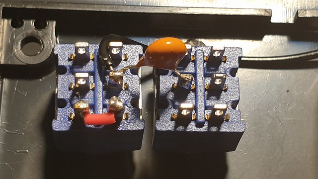
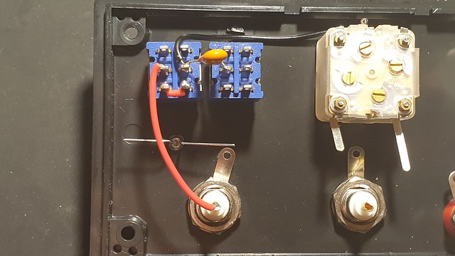
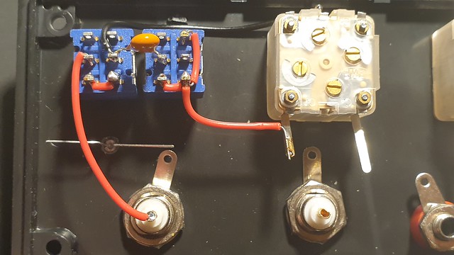
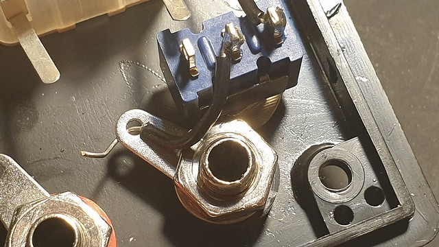
Next we put a short bridge between lower poles of the left switch and connect the left – middle pole of the left switch to it the center pin of the bnc connector.
Two more bridges on the right switch and some wire to both tabs of the capacitor.
Now we start making the ground connections. From the cathode of the LED to the GND of the BNC connectors, to,the GND of the capacitor. And from the GND of the capacotor, we make a connection with the outer pole of the switch. The middle pole of the switch we connect to tab that corresponds with the black banana socket.
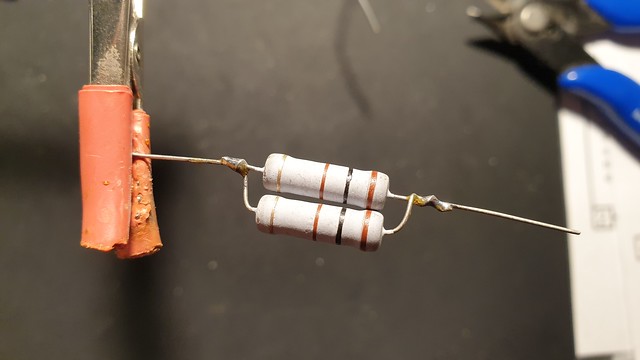
To make a 50 Ohms resistor, we put two 100 Ohms resistors in parallel and then we place them between the two upper poles of the left switch, and the upper left pole of the left switch and the anode of the LED. We don’t make the soldering on the LED yet, as we still have to add the other resistor and a loose end of the 5 turn wire of the T2 toroid.
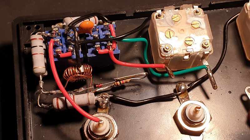
The twisted wire part of the T2 toroid is connected to the top right pole of the left switch. Because I want to make sure the twisted part will not make any shorts, I used some shrinktube to insulate it.
The loose end of the 20 turn wire is connected to one lead of the 1 KOhms resistor. The other lead of the resistor is soldered to the anode of the 1N4148 diode. The Cathode of the diode is soldered to the anode of the LED. With those connections in place, the swr measuring part of the z-match is ready.
Then it’s time to install the T1 toroiid. Easiest part to explain is to connect the ends of the black twisted wires to the red and black banana socket. Then the first tab of the green wire is to be connected to the left lead of the left capacitor. The other end of the green wire is to be connected to the right lead of the right capacitor. Now we only have two loose red wire leads left. The loose end from the left side of the toroid is to be connected to the left lead of the right capacitor. And the other red wire is to be connected to the ground tab of the right capacitor. To finish off, we need to connect the center of the right BNC connector to the red banana socket. When you’ve done this, you have finished the wiring of this z-match.
